SwitchBlox 5V Output Performance
4 min read

Author
Performance & Benchmarks
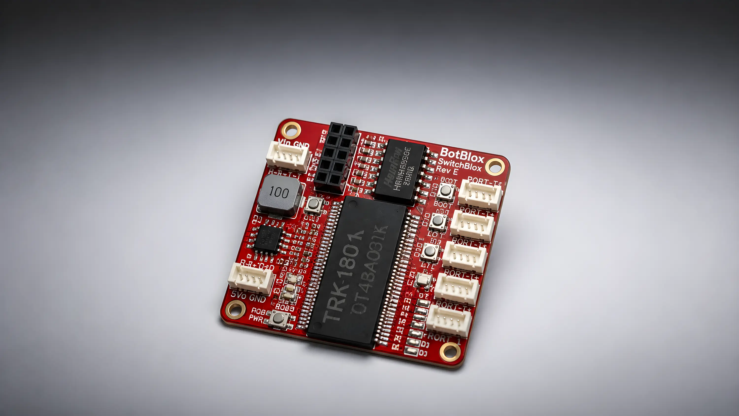
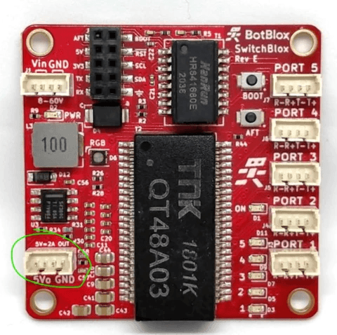
SwitchBlox includes a 5V output that can be used to power downstream devices. To help you integrate it confidently, we ran a series of tests to quantify how that output performs in terms of voltage stability and thermal behaviour under load.
All tests were conducted on SwitchBlox Rev E2. Results are expected to be broadly representative of previous revisions (excluding Rev A).
Test Setup
Ambient temperature: 25°C
Airflow: 0 LPM (no forced cooling)
SwitchBlox operation: 100 Mbps networking active between two ports
Input voltage: 32V
Results
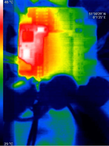
We tested four output current levels, measuring voltage ripple and temperature rise at each point :
0A:
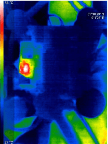
Thermal image of the board at 0A output current
0.5A:
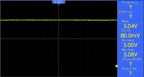
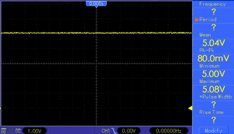
5V Output at 0.5A load current
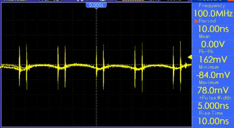
5V Output Ripple (AC Coupled oscilloscope trace) at 0.5A load current
1A:
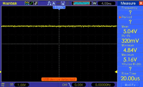
5V Output at 1A load current
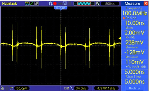
5V Output Ripple (AC Coupled oscilloscope trace) at 1A load current
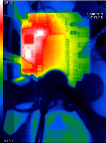
Thermal image of the board at 1A output current
2A:
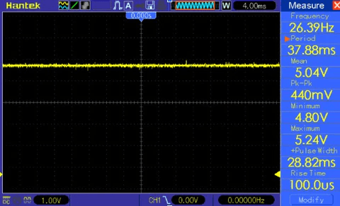
5V Output at 2A load current
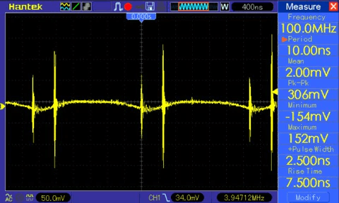
5V Output Ripple (AC Coupled oscilloscope trace) at 2A load current
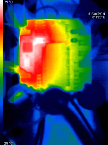
Thermal image of the board at 2A output current
Input Voltage | Airflow | Output Current | Voltage Ripple (mV) | Temperature Rise (°C) |
|---|---|---|---|---|
30V | 0 LPM | 0A | 30 | 11 |
30V | 0 LPM | 0.5A | 162 | 23 |
30V | 0 LPM | 1A | 238 | 34 |
30V | 0 LPM | 2A | 306 | 54 |
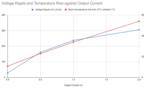
Both voltage ripple and temperature rise show a near-linear relationship with output current. The two main heat sources are the step-down regulator and the flyback diode, both rated to a maximum junction temperature of 125°C.
What This Means in Practice
At maximum load (2A), the board sees a 54°C temperature rise above ambient. Starting from 25°C, that puts the board at 79°C, well within the component ratings. If your operating environment reaches ambient temperatures around 71°C, active cooling of those two components is recommended to maintain long-term reliability.
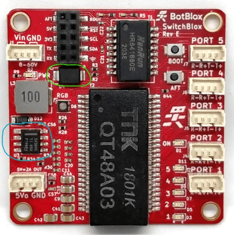
If you are not using the 5V output at all, no additional cooling is required under normal operating conditions.


