What's the Best Communication Bus for Robots and Drones?
7 min read

Author

Guides & Explainers
So you’re designing a robot or drone, you’ve got your motors, some cameras and sensors, and an embedded computer to make it all work. Pretty early on you’re going to have to figure out how to connect it all together.
In other words, you’re going to need to pick a physical communication bus to transfer data between everything inside the robot. This is not an easy choice, but it’s a really important one. There are many options, and you’ll want to get this right to ensure your system architecture can handle expected data rates, remain robust, and scale for the future.
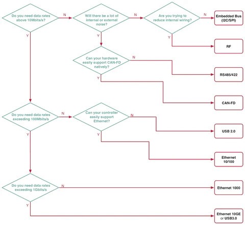
So what are the options, and how do you pick the right one? There is no one-size-fits-all answer. Are you using cameras distributed across the robot? You’ll need a fast data rate. Is your robot going to be deployed in challenging environments? Robustness will be key. In this article we’ll evaluate the most viable options and answer the question: what is the best communication bus for robots and drones?
What Makes a Good Communication Bus?
When designing robots and drones, these are the criteria that matter most:
Physical Robustness — Are the cables and connectors robust against strain and abrasion?
Noise Immunity — Large spinning motors can introduce significant noise into circuits.
Data Rate — Sensors like cameras require high throughput.
Ease of Design — Does your hardware natively support the bus? If not, how complex is the integration?
Open Software — You don’t want to write low-level drivers from scratch.
Size — Tight spaces call for compact connectors and cables.
Cost — Higher data rates generally mean higher cost.
The Options
Rather than surveying hundreds of buses, let’s focus on the most widely used — which also means the most hardware and software support available:
Embedded buses: SPI, I2C
USB 2.0
USB 3.0 (and onwards)
Ethernet 10BASE/100BASE
Ethernet 1000BASE
Ethernet 10G
CAN-FD
RS485/422
RF (Wi-Fi / Bluetooth)
Evaluating the Options
Bus | Physical Robustness | Noise Immunity | Max Data Rate | Ease of Design | Open Software | Size | Cost |
|---|---|---|---|---|---|---|---|
I2C / SPI | Design-dependent | Poor | 20 Mbit/s | Easy | Good | Design-dependent | Low |
USB 2.0 | Good | Good | 480 Mbit/s | OK | OK | Small | Moderate |
USB 3.0+ | OK | OK | 10 Gbit/s | Hard | Hard | Moderate | High |
Ethernet 10BASE/100BASE | Good | Good | 100 Mbit/s | OK | OK | Large | Moderate |
Ethernet 1000BASE | Good | Good | 1 Gbit/s | OK | OK | Large | Moderate |
Ethernet 10G | Good | Good | 10 Gbit/s | Hard | Hard | Huge | High |
CAN-FD | Design-dependent | Excellent | 8 Mbit/s | Easy | OK | Design-dependent | Low |
RS485/422 | Design-dependent | Excellent | 10 Mbit/s | Easy | Good | Design-dependent | Low |
RF | Good | Poor | 54 Mbit/s | Hard | Good | Small (wireless) | Moderate |
Data Rate Reference: Common Robotics Components
Before walking through examples, here are typical data rates for common components:
Device | Update Rate | Packet Size | Estimated Data Rate |
|---|---|---|---|
High-speed motor controller | 500 Hz | 16 bytes | ~64 Kbit/s |
Main embedded computer | 10 Hz | 265 bytes | ~20 Kbit/s |
Low-level MCU with sensors | 10 Hz | 32 bytes | ~2.6 Kbit/s |
Small OLED display | 60 Hz | 1 KB | ~48 Kbit/s |
HD 1080p camera | 30 Hz | ~512 KB (compressed) | ~245 Mbit/s |
640×480 camera | 60 Hz | ~80 KB | ~39 Mbit/s |
Case Study 1 — High-Precision Rover With 1 HD + 4 480p Cameras
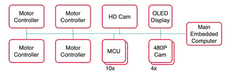
System:
4× high-speed motor controllers: 0.256 Mbit/s
1× main embedded computer: 0.020 Mbit/s
10× low-level MCUs with sensors: 0.026 Mbit/s
1× OLED display: 0.048 Mbit/s
1× HD 1080p camera: 245 Mbit/s
4× 640×480 cameras: 156 Mbit/s
Total required: ~402 Mbit/s
Viable options:
USB 2.0 — Adequate at 480 Mbit/s max, but leaves little headroom and requires hub circuitry on every board.
USB 3.0 — More headroom, but still requires hubs and has moderate noise immunity.
Ethernet 1000BASE — The best choice here. Robust, fast, and well-supported. Requires switches to tie the network together; RJ45 connectors are bulky, but the tradeoff is worth it.
Ethernet 10G — Overkill for this application and significantly more expensive.
Verdict: Ethernet 1000BASE.
Case Study 2 — Same Rover, Optimised Architecture
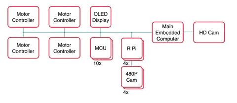
In Case Study 1, cameras accounted for 401 of the 402 Mbit/s required. The fix: move the HD camera to a dedicated connection on the embedded computer, and offload each 480p camera to its own Raspberry Pi (or equivalent). These nodes then send only high-level control data over the shared bus — not raw video.
Revised system:
4× high-speed motor controllers: 0.256 Mbit/s
1× main embedded computer: 0.020 Mbit/s
4× Raspberry Pi nodes: 0.082 Mbit/s
10× low-level MCUs with sensors: 0.026 Mbit/s
1× OLED display: 0.048 Mbit/s
Total required: ~0.74 Mbit/s
This opens up far more options:
I2C/SPI/UART — Could work, but four spinning motors introduce noise. Not ideal.
USB 2.0/3.0 — Viable, but hub circuitry on every board adds complexity and cost.
Ethernet 10BASE/100BASE — Excellent choice. Robust, widely supported, and vastly over-specced for 0.74 Mbit/s — leaving room to grow.
CAN-FD — Also excellent. Fast, highly noise-immune, no switch circuitry needed. Not all embedded computers support it natively, but robotics-focused hardware increasingly does.
RS485/422 — Widely used in industry. Most embedded computers can use a standard serial port with a transceiver to support it. Solid choice for deterministic, low-bandwidth communication.
RF (Wi-Fi) — Technically possible, but motors cause interference and metal enclosures attenuate the signal. Not recommended.
Verdict: Ethernet 10BASE/100BASE for scalability; RS485 or CAN-FD if bandwidth needs are fixed.
Key Takeaways
Calculate your maximum data rate based on all connected components.
Look for opportunities to restructure your architecture to reduce bus load — offloading cameras is often the single biggest win.
Eliminate buses that can’t meet your data rate requirements.
Factor in noise immunity — motors are the main culprit in most robot and drone designs.
Favour buses with strong off-the-shelf hardware and software support to reduce integration time.
Prototype and test before committing. Redesigning around a different bus mid-project is painful.
The most widely used buses in industrial robots are Ethernet 10/100, Ethernet 1000BASE, and CAN-FD.